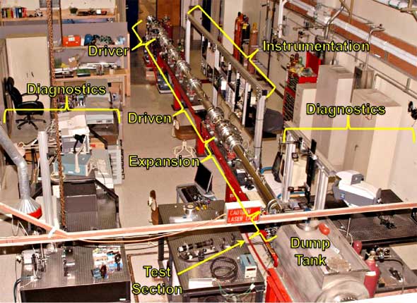
| The Stanford 6” Expansion Tube Facility (shown in the photograph on the left) is located in the High Temperature Gasdynamics Laboratory at Stanford University. The operation principle and the theoretical analysis of an expansion tube as a means to generate high-enthalpy, high-speed flows for the study of hypersonic flows can be found in Trimpi (1962). A detailed description of this flow facility, its characterization and performance can be found in the work of Heltsley et al. (2006) and Heltsley (2010). An expansion tube is a short duration, impulse flow facility used to produce high-enthalpy, moderate to high Mach number flow conditions replicating a wide range of aerothermal conditions found in many propulsion and space applications. In general, this type of flow facilities can generate flow conditions for the aero-thermodynamic study of both vehicle external and internal flows. However, this particular system is specifically optimized to generate the aero-thermodynamic conditions necessary for the study of supersonic combustion within the wide spectrum of operating conditions of a typical scramjet engine of a hypothetical hypersonic vehicle. |
| |
 |
| |
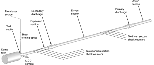
| As shown in the schematic diagram below , the expansion tube is composed of three circular sections 14 cm in (inner) diameter: a driver, a driven and an expansion (or acceleration) sections, respectively. The expansion section terminates into the test section where the test article is placed and which is open onto a vacuum dump tank. The three sections are separated by diaphragm assemblies and are independently pressurized with the gas of interest. The driven section is filled with the test gas of interest (typically air) whereas the driven and expansion sections are filled with low molecular weight gases (typically Helium). |
| |
 |
| |
| The test begins when bursting of the primary diaphragm is induced which result in the formation of a primary shock wave that travels through the driven (test) gas. Once the primary shock wave reaches the secondary diaphragm, it instantaneously ruptures the thin diaphragm, resulting in the formation of a secondary shock wave that propagates into the expansion section and of a constant area unsteady expansion that propagates back into the test gas. The test gas, which was originally contained in the driven section, is therefore first processed (compressed, heated and set into motion toward the test section) by the primary shock generated by the rupture of the primary diaphragm, and it is then reprocessed by the unsteady, constant area expansion occurring when the primary shock ruptures the secondary diaphragm. This latter process accelerate and cools the test gas to the final aerothermodynamic state. The processed test gas flows at the end of the expansion tube and enters the test section where the test article is secured. The final aerothermodynamic state (p, T, M) of the test gas can be adjusted by changing the filling pressure of each of the three sections, allowing for a wide range of conditions to be explored. Furthermore, since the test gas is not exposed to high intermediate temperatures, the chemistry of the incoming flow can be more effectively controlled. The “test time”, defined as the portion of the total flow time over the test model where (quasi-)steady test gas conditions are observed is typically on the order of 0.1-0.5 ms. |
| |
 |
| |
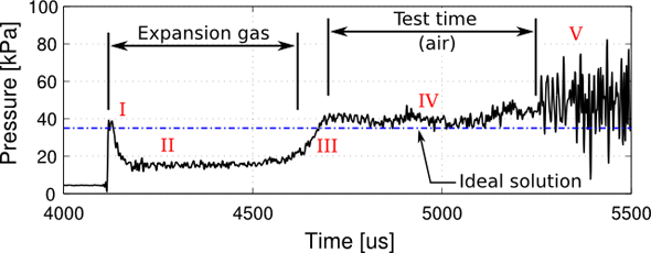
| The operation of an expansion tube is intrinsically an unsteady, short-duration process. To demonstrate the processes occurring in the test section (at the test article location, for example), a time history of the wall pressure variation on a flat plate mounted in the test section at the exit plane of the expansion tube is shown in the figure to the left for a representative test case. The wall pressure was measured with a fast-response pressure transducer embedded in the flat plate. The time axis refers to the initiation of the test and corresponds to the first detection of the primary shock in the driven section. Five relevant events in the evolution of the flow can be identified from the trace. For the particular condition considered in this figure, the expansion gas (Helium) arrives at about 4.1 ms (I) and undergoes an expansion at the exit of the expansion tube into the test section due to a pressure mismatch (II). The contact surface between expansion and test (air) gas arrives at about 4.7 ms (III) and the test gas follows (IV) till an flow disturbance arrives at about 5.25 ms (V) that terminates the test time (defined between III and V). For this particular conditions, the test time is on the order of 0.5 ms. |