| An indraft laboratory scale wind tunnel is used to generate a relatively uniform supersonic flow (Ma ~ 5). The flow in the tunnel, in the presence of a transverse jet, is characterized by Planar Laser Rayleigh Scattering (PLRS), Particle Image Velocimetry (PIV) and Schlieren imaging. |
| |
 |
| |
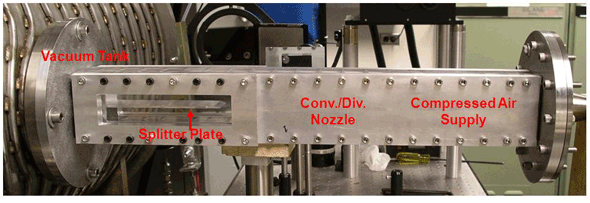
| High pressure air (P0 = 350 kPa and T0 = 300 K) containing CO2 (approximately 25 % by volume) expands through a converging/diverging nozzle (25:1 area ratio) to establish a relatively uniform Ma = 5 flow in a rectangular test section (4 cm × 4 cm cross-sectional area). The exit of the tunnel is connected to a vacuum tank that accommodates the incoming mass flow for approximately 10 seconds of run time (when with a subsidiary dump tank). During this run time, the vacuum tank pressure is maintained at values lower than the static pressure in the test section. A honeycomb of 2.5 cm in length and 3 mm hexagonal cells is placed upstream of the converging nozzle to suppress flow swirling, mostly generated at various junctions in the gas stream inlet piping. The static pressure and temperature of the flow in the test section is approximately 1 kPa and 50 K, respectively. |
| |
| A detailed characterization of the variation in Mach number of the flow across the test section is carried out by measuring the shock angle from a sharp leading 12° wedge using Schlieren photography. The measured Mach number midway across the tunnel is Ma = 4.9, with a 5 % variation wall to wall (boundary layers were not resolved). Windows on both sides of the test section and transparent upper/lower walls allow optical access. In the baseline configuration, a 3 mm thick splitter plate(aluminum plate), having a sharp but wedged leading edge and a transparent slotof an embedded acrylic plate divides the test section into two parts of equal cross sectional area, and serves as an intake lip for the defined inlet. This asymmetric design (with the 12° angled wedge in the top half of the channel) is used to generate a relatively shock-free flow in the lower half while it causes a series of oblique shock reflections in the upper half.Static pressure traces are recorded on the bottom wall of the tunnel straddling a jet injection nozzle, using eight fast response (100 kHz) pressure sensors (S1 – S8: PCB Piezotronics, Model 113A26). The sensors and the jet injection nozzle, placed between S4 and S5, are separated by 15 mm along the centerline of the bottom wall parallel to the freestream flow direction: S1 and S8 are located 60 mm upstream and downstream from the nozzle, respectively. The distance between the tip of the splitter plate (270 mm downstream from the converging/diverging nozzle throat) and the jet nozzle is 75 mm. |