| A transverse hydrogen jet in supersonic crossflow is taken as a representative unit-problem system. An underexpanded sonic hydrogen jet is formed by a contoured converging nozzle on a flat plate in a high-enthalpy crossflow. The crossflow (static) pressure, temperature and Mach number are selected to be aerothermal conditions that are representative of conditions found in a scramjet combustor of a generic hypersonic vehicle. The work is carried out in the Stanford 6" Expansion Tube Facility where advanced laser-based diagnostics techniques are developed and applied for the investigation of the system. |
| |
| |
| Objectives |
This project is in direct support of the mixing and combustion modeling efforts of the Center. The objectives of the work are three-fold:
- Investigate mixing, ignition, combustion, flame holding and stabilization processes in the supersonic regime at the unit problem/device-sub-system level
- Improve the physical understanding of and quantify mixing and combustion processes at supersonic speeds
- Provide data for mixing and combustion model validation as a sub-part of the heat release model
|
| |
| |
| Transverse jet in supersonic crossflow |
| A jet in crossflow (JICF) is a fundamental canonical flow for the investigation of turbulent mixing and combustion. It is of relative simplicity yet retaining many features of interest, such as three-dimensionality, separation and recirculation regions, wall-bounded effects, and vortical flows. Furthermore, it maintains some level of practical relevance for engineering applications being found in many technological processes. A wide body of work has been conducted to characterize and study this system, both at low- and high- (supersonic) speeds, especially under nonreacting conditions. Reacting transverse jets in the supersonic regime have, however, received much less attention, partially due to the requirements and complexity to sustain combustion in a supersonic flow (Lee et al., 1992; McMillin et al., 1994; Ben-Yakar et al., 1998; Heltsley et al., 2007). |
| |
In addition 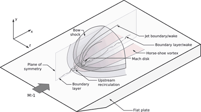 to the traditional vortical structures generated by the interaction of the jet with the crossflow that are present in low-speed JICF, the supersonic counterpart has many more features. As shown in the figure on the right, jets in supersonic crossflows are characterized by a three-dimensional bow shock generated by the blockage effect of the issuing jet and that wraps around the base of the jet, the upstream recirculation region caused by the bow-shock-induced boundary layer separation, and a recirculation region just downstream of the injection porthole. Furthermore, the incoming boundary layer experiences an interaction with the bow shock that can extend further away form the immediate vicinity of the injector. This interaction can have significant impact on mixing, ignition and boundary layer dynamics. to the traditional vortical structures generated by the interaction of the jet with the crossflow that are present in low-speed JICF, the supersonic counterpart has many more features. As shown in the figure on the right, jets in supersonic crossflows are characterized by a three-dimensional bow shock generated by the blockage effect of the issuing jet and that wraps around the base of the jet, the upstream recirculation region caused by the bow-shock-induced boundary layer separation, and a recirculation region just downstream of the injection porthole. Furthermore, the incoming boundary layer experiences an interaction with the bow shock that can extend further away form the immediate vicinity of the injector. This interaction can have significant impact on mixing, ignition and boundary layer dynamics. |
| |
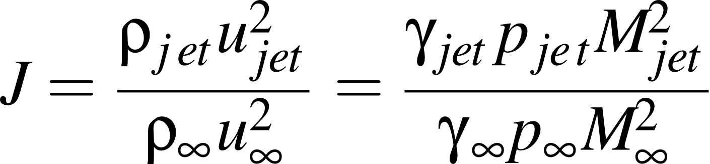
| Global characteristics of JICF's, such as penetration, for example, have been found to primarily depend on a single parameter (see for example Margason, 1993, for low speed JICF), the so-called jet-to-crossflow momentum flux ratio J defined as |
| |
 |
| |
| This parameter is also found to describe the global features of the supersonic counterpart (see, for example, Portz and Segal, 2006, regarding jet penetration). |
| |
| Some of the most recent work aimed at investigating the effect of J on ignition and reaction zone structure of JICF using a series of diagnostics techniques while maintaining the freestream conditions constant. The ongoing experiments are conducted at the Stanford 6" Expansion Tube Facility located in the High Temperature Gasdynamics Laboratory. A brief description of the flow facility and its principle of operation can be found here. |
| |
| |
| Experimental techniques |
The following measurement techniques are used in this work:
- High-speed Schlieren imaging: it is a line-of-sight integrated imaging technique and is used to visualize the flow and shock structure around the transverse jet.
- OH* chemiluminescence imaging: it is a line-of-sight integrated imaging technique and is used to visualize the overall characteristics of the reacting jet. OH* is an approximate marker of heat release.
- OH planar laser-induced fluorescence (PLIF) imaging: OH is a major intermediate product of combustion that naturally occurs in reacting flows (especially in H2/O2 chemistry). Its presence in the reaction zone makes it a convenient marker of the instantaneous reaction zone but also of regions where hot combustion products dwell.
- Surface pressure measurements using fast-response pressure transducers: pressure measurements are used to characterize the inflow and boundary conditions, but also to investigate the dynamics of fuel injection and of the transverse jet.
|
| |
| |
| Inflow, boundary conditions, calibrations |
| Because a strong motivation for this work is model validation, a significant effort is placed on defining and characterizing the inflow and boundary conditions of the experiments as well as on assessing the different calibrations that are used in the work (such as injector calibration, for example). In the most recent work we have identified a single freestream condition representative of the conditions in the scramjet engine of a hypersonic vehicle traveling at Mach 8 and 30 km altitude. The nominal conditions, estimated from direct observations on directly measurable quantities, are the following: P = 40 (+/- 3) kPa, M = 2.4 (+/- 0.05), and T = 1500 K. |
| |
Two different approaches have been followed to calibrate and characterized the fuel injection system. Assuming underexpanded sonic injection, the primary quantity relevant to characterize the injection system (knowing the geometry of the contoured injector) is the jet stagnation pressure P0. This quantity is estimated indirectly and directly with two different approaches:
- indirectly by using known relations between observable quantities (Mach disk stand-off distance) and the jet stagnation-to-ambient pressure ratio (Ashkenas and Sherman, 1962; Crist et al., 1968);
- directly by measuring the time variation of the jet stagnation pressure in the plenum of the injector.
This approach allowed us to identify discrepancies in the calibration procedure and better understand the fuel injection scheme in the experiment. As part of this effort, an investigation of the formation of the jet under quiescent conditions was also carried out as part of the LES fuel injection modeling. |
| |
| |
| Representative results |
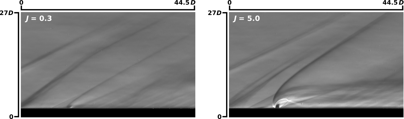
| A representative time-averaged (exposure 50 us) Schlieren image showing the average flow structure of the transverse jet is shown below. A transverse jet at J=0.3 (left) and J=5.0 (right) are shown. Flow is from left to right. The freestream conditions are P=40 kPa, T~1500 K and M=2.4. The main flow features schematically shown above can be recognized: the bow shock, separation shock, an incoming thin boundary layer, the distorted barrel shock and the envelope of the jet shear layer. |
| |
 |
| |
| |
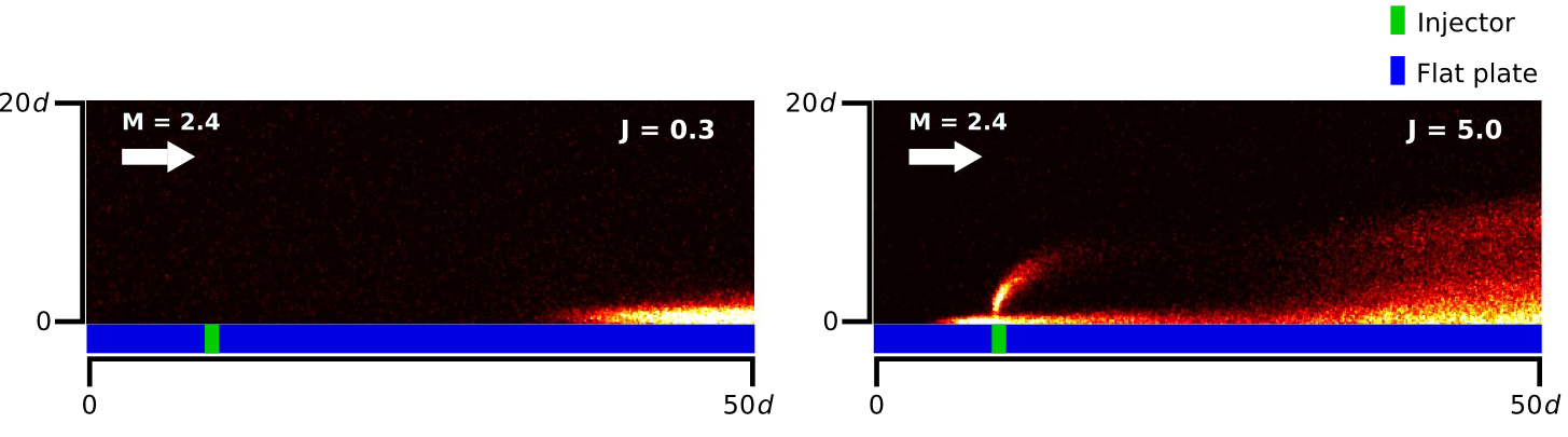
| The next figure shows a time-averaged (100 µs), line-of-sight integrated OH* chemiluminescence image showing the location and intensity of the burning region for the same cases shown in the previous figure. At low values of J the jet is confined close to the wall, with minimal penetration. Ignition occurs only in the wake of the jet. On the contrary, at high J, strong penentration occurs that induces a strong bow shock and promotes near field ignition. Note also the burning regions upstream of the injection point. At high J, heat is release both at the wall, in the wake of the jet, and in the shear layer. However, it appears that most of the heat release seems to occur close to the bounding surface, not in the body of the jet. |
| |
 |
| |
| |
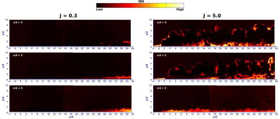
| Details of the instantaneous reaction zone are investigated using OH PLIF. Contrary to the other imaging techniques used in the study, OH PLIF is capable of selecting a planar region of the flow where the reaction zone and regions of hot post-combustion gases exists. A typical example of the OH zones as rendered by OH PLIF on selected side-view planes is shown in the next figure. This figure shows cuts through the reacting jet at J=0.3 (left column) and J=5.0 (right column) on different planes: at z/D = 0 (centerplane of the jet), z/D = 2 and z/D=5. This type of results enables us to clearly identify the ignition points, the structure of the reacting regions, and the locations where chemical reactions occur. As the OH* chemiluminescence results suggested, ignition at low values of J occurs only in the wake and is mostly confined at the wall where the wake of the jet and the wall boundary layer are strongly coupled. For high values of J, both the shear layer and the wall regions are reacting. The most intense reacting regions, however, remain regions near the wall. Note also that the reacting wake/boundary layer extends laterally from the immediate jet wake and remains confined in the boundary layer region. |
| |
 |
| |
| |
[an error occurred while processing this directive]