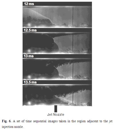
Time synchronized Rayleigh scattering images of the flow evolution near the vicinity ofthe jet injection are shown in Fig. 6. In the 12 ms image, the air jetis clearly entrained by the flow but not yet filling the tunnel, and the pressure disturbance (initially recorded at S8 at approximately 10 ms) propagating upstream in the wall boundary layer, will have just arrived near the vicinity of the injection point. The bow shock generated by the jet strikes the upper surface inducing boundary layer thickening due to local compression (dark region on upper surface (i.e., lower surface of the splitter plate). In the subsequent frames (12.5 ms – 13.5 ms), the laminar boundary layer on the upper surface thickens while propagating upstream (presumably due to the propagation of pressure disturbances along the upper boundary layer) and eventually becomes turbulent. On the bottom wall, by 13 ms, we see the development of a turbulent boundary layer just upstream of the jet and bow shock and the formation of an unstart shock. By 13.5 ms, this unstart shock is well developed, and begins to interact with the upper, growing boundary layer. As we will see in Fig. 7, the injected mass expands into the boundary layer region behind the unstart shock, driving the shock forward towards the inlet of the channel. |
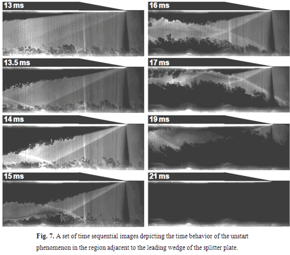
| Time synchronized Rayleigh scattering images of the flow evolution near the vicinity of the splitter plate tip are shown in Fig. 7. We see that by 13 ms, the boundary layer on the lower splitter plate surface has increased in thickness and generated a weak oblique shock. By 13.5 ms, this boundary layer has reached the splitter plate tip, thickened on the splitter plate, and the resulting shockwave appears stronger. The lower unstart shock appears in this spatial window at 13.5 ms, and by comparing subsequent frames, appears to propagate upstream together with the evolving turbulent boundary layer on the bottom wall. Again, as was seen in Fig. 5, the refracted unstart shock clearly suppresses boundary layer development on the surface of the splitter plate (during the time period between 15 ms and 17 ms). There may also be a slight suppression of the lower wall boundary layer due to interactions with the shock emanating from the splitter plate tip. At 19 ms, the unstart shock leaves the region of interest and the turbulent boundary layer on the bottom wall grows in extent to reach the splitter plate surface near the splitter plate leading edge. By 20 ms, the lower half of the tunnel is nearly completely unstarted and occupied by high pressure (and presumably high temperature) flow as evidenced by the complete absence of condensed CO2 particles. |
| The speed of the unstart shock can be determined by the movement of the shock between frames captured at 13.5 ms and 16 ms. Under the conditions studied, the unstart shock propagates at approximately 15 m/s. This speed is slower than that of the propagation of the wall pressure characterized by the wall pressure sensors, as shown in Fig. 3 (22 m/s). The speed of the unstart shock is determined by the growth of the thick turbulent boundary layer region on the lower wall as it thickens. While it appears as though the two speeds are very different, we surmise that the thickening of the boundary layer and its movement, generating the unstart shock, is a consequence of the pressure wave that propagates upstream along the boundary layer. |